Installation Diagrams
Below are wiring diagrams from our vehicle. Please do not let them
scare you if you are not use to looking at these. The breakdown is
actually quite simple.
When wiring 12v DC items, you have a positive wire (usually red) and
negative (usually black). The wires supplied with these lights actually
use black with white stripe for positive and black for negative. Some
wires will need to be extended to reach the locations below.
The first diagram shows that the wires you will need to access are
located in the driver's side and passenger side, close to the door.
We'll only be looking at the big plug on both sides.
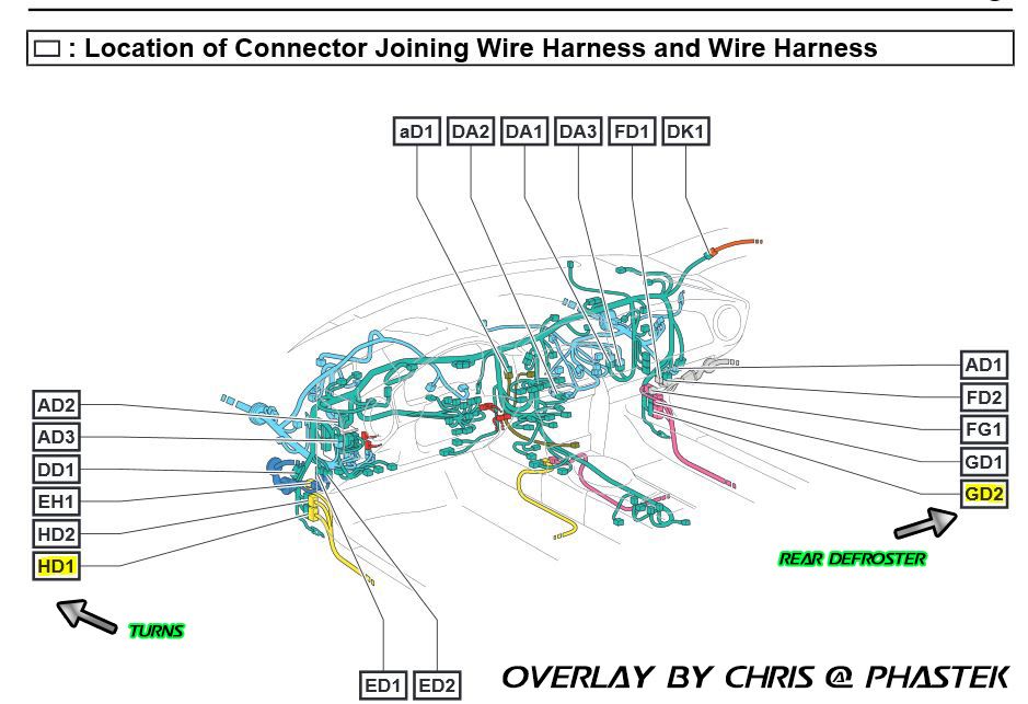
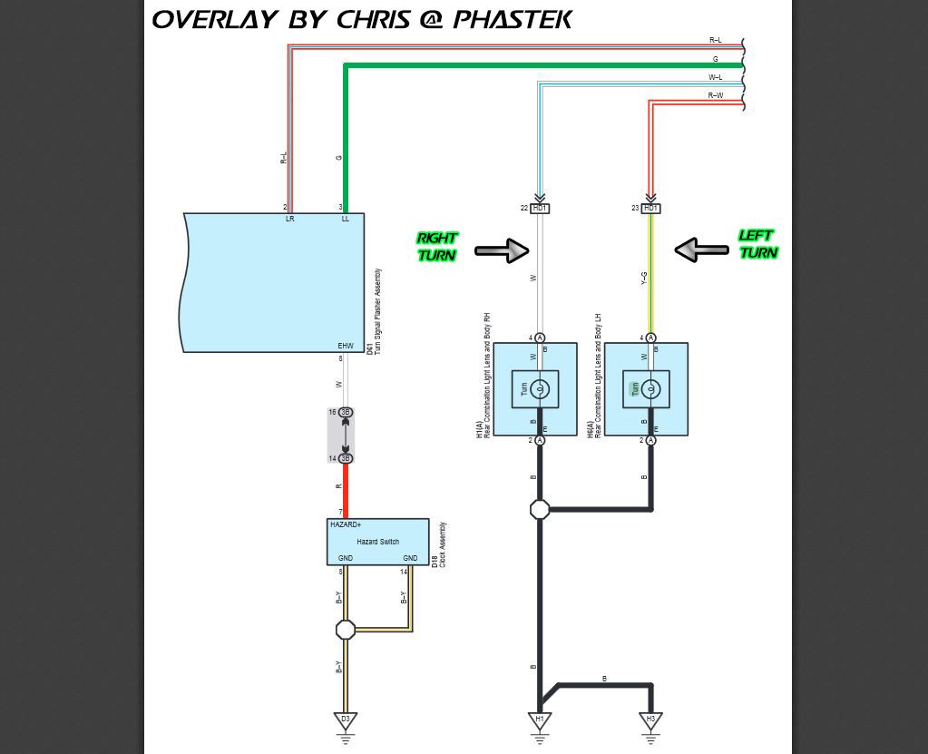
The wires below are located in HD1. This is the plug on the driver's side.
- The white wire is the passenger side (right) turn signal (positive).
- The yellow wire w/ green stripe is the driver's (left) turn signal (positive).
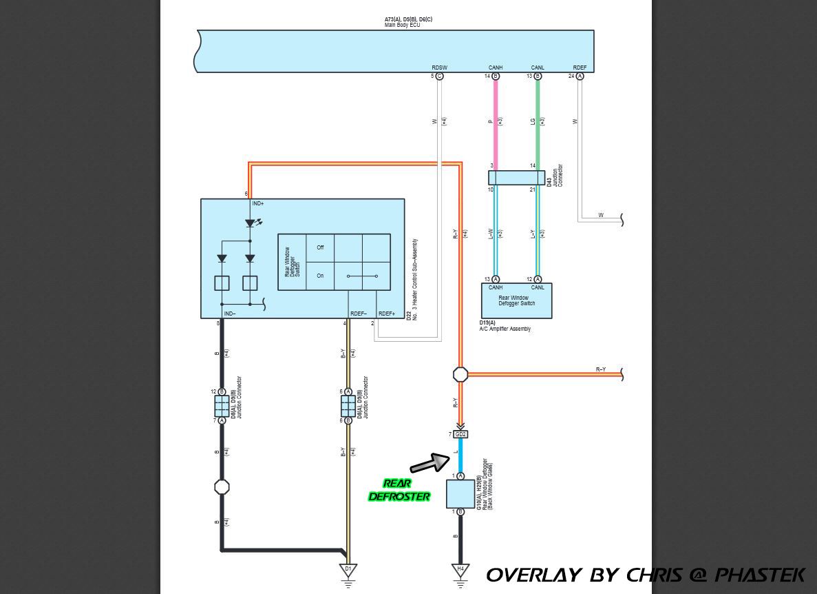
For vehicles with factory heated mirrors, these are controlled by the
rear window defroster switch. It only makes sense for those that don't
have heated mirrors to tap into the same circuit.
The positive wire for this will be light blue in color (EDIT: it can be a darker blue. Note that the wire on the other side of the harness is yellow with red stripe) and located in
harness GD2 which is the big plug on the passenger side. You can get 1 T
tap (I prefer these other other wire taps) and place two wires in it.
One will go to the driver's side and the other to the passenger side.
Those will be the positive wires.
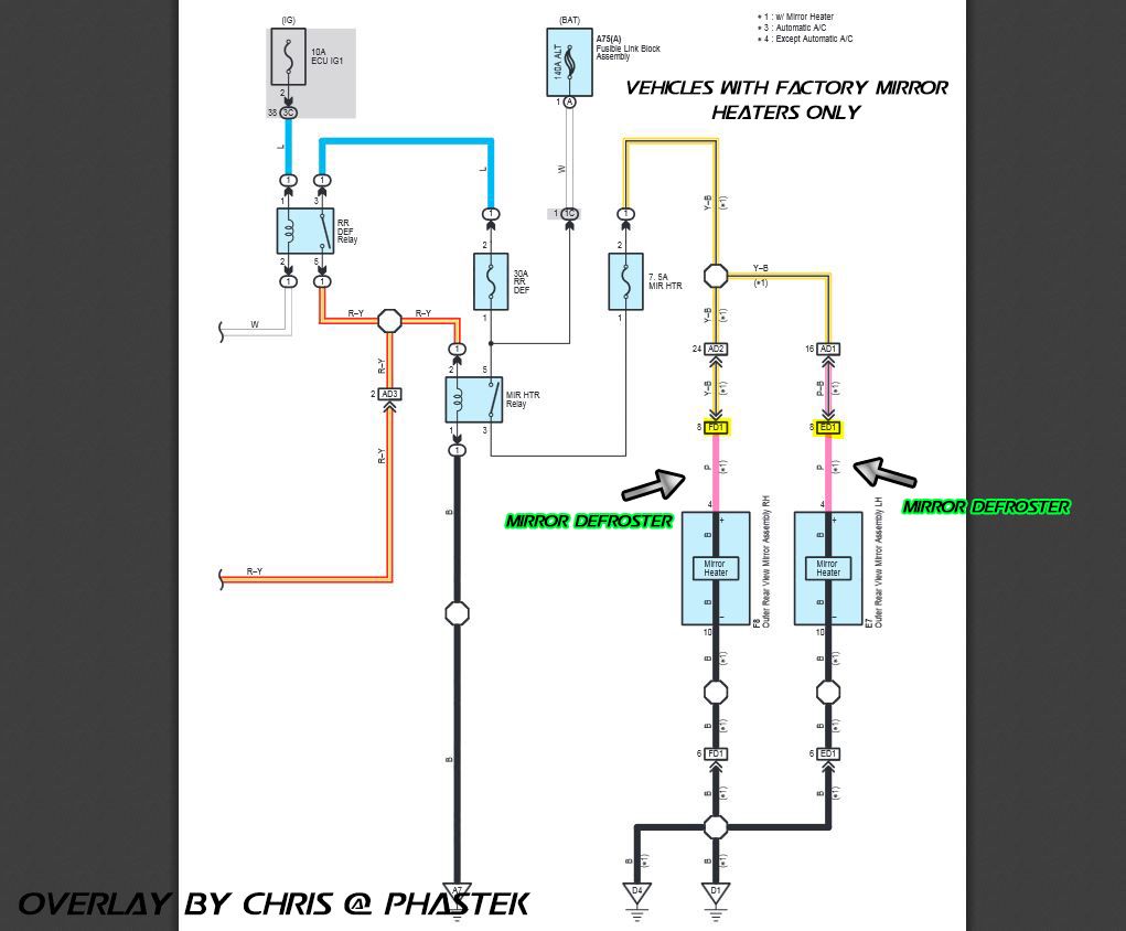
Vehicles with factory mirror heaters will have the wires in the mirror
assembly already. The positive (+) wire for these are pink in color.
As far as ground points (for the negative), you can find an existing
negative wire, use an existing bolt and eyelet grounding end (see image
below), or tap into the body to ground everything.
I would use two ground points total. One for the driver's side wiring and one for the passenger side wiring.
